Fundamentals of Capacitive Discharge Resistance Welding
 Capacitive discharge resistance welding uses capacitors to store energy for quick release. Figure 1 shows a typical capacitor discharge curve. Capacitive resistance welders, also called capacitive discharge or CD welders, have many advantages over other welder types. Weld nugget formation takes place during the first few milli-seconds of the welding process. A CD welder allows extremely fast energy release with large peak currents. More of the energy goes into weld formation and less into heating surrounding material. The heat affected zone, where the properties of the metal have been changed by rapid heating and cooling, is localized to a small area around the weld spot. The quick discharge rate of CD welders also allows electrically and thermally conductive materials, such as copper or aluminum, to be welded. Capacitive welders deliver repeatable welds even during line voltage fluctuations because weld energy is stored before use. Capacitive discharge resistance welding uses capacitors to store energy for quick release. Figure 1 shows a typical capacitor discharge curve. Capacitive resistance welders, also called capacitive discharge or CD welders, have many advantages over other welder types. Weld nugget formation takes place during the first few milli-seconds of the welding process. A CD welder allows extremely fast energy release with large peak currents. More of the energy goes into weld formation and less into heating surrounding material. The heat affected zone, where the properties of the metal have been changed by rapid heating and cooling, is localized to a small area around the weld spot. The quick discharge rate of CD welders also allows electrically and thermally conductive materials, such as copper or aluminum, to be welded. Capacitive welders deliver repeatable welds even during line voltage fluctuations because weld energy is stored before use.
Weld Formation
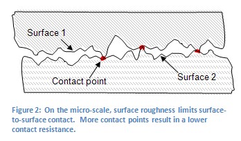
Spot welding relies on metal resistivity (resistance) to heat and fuse metal. A large current is passed through the work piece metal. Energy is dissipated due to the metal resistance in the form of heat which melts and fuses weld materials. There are two phases to the melting process. The welder must overcome both the material contact resistance and the bulk resistance of the material. Figure 2 shows an example of a micro-scale surface profile. On the micro-scale, material surfaces are rough and only contact in a limited number of locations. In the first few milli-seconds of weld formation the high-resistance metal bridges melt allowing other bridges to come into contact to continue the melting process. When all of the bridges have fused the contact resistance is zero. The bulk resistance of the metal then plays the final role in the weld formation.

Several other factors play a part in the contact resistance. The larger the contact resistance the hotter the resultant weld. On the micro-scale, contact resistance is reduced when more metal bridges or contact points are formed (see Figure 2). Using more electrode pressure creates more metal bridges. This results in a lower contact resistance and a cooler weld. Conversely, light electrode pressure results in less metal contact, higher resistance, and a hotter weld. An appropriate amount of pressure should be used to insure good weld strength.
Weld Configurations
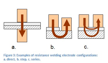
Figure 3 shows several electrode configurations used in resistance welding. Figure 3a is called a direct weld. Current is passed from one electrode, through both work pieces and out an opposing electrode. Figure 3b shows a step electrode configuration. This configuration is used when there is access to only one side of the work piece and an electrode can be placed on both materials. Figure 3c is a series configuration. Electrodes can only be placed on one metal surface from one side. Current is divided between the two parts. This weld configuration requires more weld energy.

Determining Weld Energy
A capacitive discharge welder controls the voltage of the welding capacitors. However, the energy stored in the capacitor is a function of the voltage squared (E = (1/2)*C*V2). This relation states that a small difference in voltage makes a large difference in weld energy. Sunstone CD150DP - CD750DP welders have a voltage adjustment dial. The power stored in the welder can be found by referring to the equation above or by visiting Table 1.
Using Sunstone Dual Pulse Welders
Weld Energy Indication
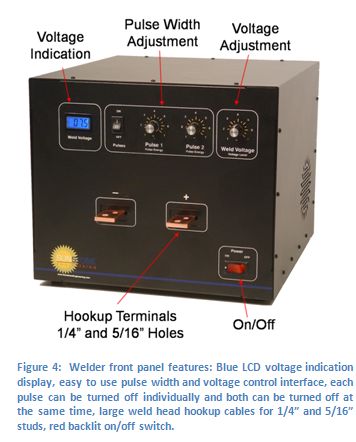
Figure 4 shows the Sunstone Engineering Dual Pulse CD welder front panel. Weld voltage is indicated with a blue backlit LCD display. To convert this value to watts*seconds (joules) use Eqn. 1 or see Table 2 for a simplified list.

 Pulse Control Pulse Control
Sunstone Dual Pulse welders have two knobs for pulse energy control. Each pulse can be adjusted separately or turned off if desired. Pulse 1 is adjustable between 1% and 50% of the total stored energy. Pulse 2 is adjustable between 1% and 100% of the stored energy. Please note that when used in dual pulse mode the Pulse 2 energy level represents the percent of remaining power. For example if Pulse 1 was set to 25% the Pulse 2 setting would actually be taken from the remaining 75% of the set-point energy.
Energy Adjustment
Each Sunstone welder is infinitely adjustable between its minimum and maximum energy. The CD150DP - CD750DP have weld repetition rates of up to 166 welds/min (the hardware defined limit). See Table 2 for additional details on weld repetition rates. The weld voltage knob is used to set the total welder energy storage (see Table 1 and Eqn. 1) and is also used to set the peak weld current (see Table 2). The pulse widths are then adjusted to provide the appropriate weld energy released during each weld.
Weld Actuation
The welders are actuated by means of an external trigger port located on the back of the welder (see Figure 5). The trigger uses a DIN 3 connector and requires shielded wire. Figure 6 shows the proper pin placement for custom external trigger cables (shown for welder back panel connector). The standard external trigger cable connector is an SD-30LP made by CUI Inc.
Weld Attachments
Sunstone Engineering produces a variety of welding hand pieces and weld heads to accommodate a diverse range of welding applications. Hand piece welding attachments allow ease of use and versatility, while fixed weld heads provide control and precision. Cabling between welder and weld head is important in determining peak weld current and adjusting weld pulse timing. Table xx indicates the Pulse 1 and 2 settings to be used with different cabling.
Voltage and Power Requirements
The CD150DP - CD750DP use 110VAC wall power. If using the welder in a country where 220VAC etc. wall power is used, a voltage transformer can be purchased from Sunstone Engineering. The welder uses a 6mm x 30mm 6A fuse. A 750W wall circuit should be used to run the welder.
Using the Dual Pulse Weld Function
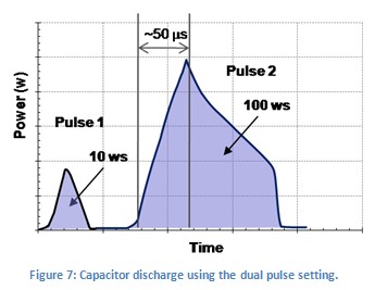
Using multiple current pulses increases weld quality. In dual pulse mode Sunstone welders will fire twice from a single actuation. The first pulse is used to remove surface inconsistencies and contaminants. This initial burst of energy displaces oils and breaks through oxide layers. The pulse also seats the welding electrodes. The second pulse is done at a much higher energy level (watt*seconds) and performs the actual weld. Figure 7 shows what the welder discharge curve would look like using the dual pulse setting as outlined above.

Setting Pulse 1 and 2
The Pulse 1 energy setting should be chosen such that the parts adhere weakly. To determine Pulse 1, turn off Pulse 2 and do a series of test welds starting at a low pulse energy setting. Increase the pulse energy 3-5% every test until the parts just stick together. Pulse 1 energy should then be decreased by 3-5%. Pulse 2 should then be set at a level 4 - 5 times that of Pulse 1. A test weld should be performed and pulled apart to determine weld strength. A nickel strip to nickel plated steel weld, typically seen in battery pack manufacturing, should pull apart leaving holes in the thin nickel metal and leaving the weld nuggets on the battery terminal. Thicker materials should be pulled with a specific pull force requirement in mind.
SAFETY
Please follow these points to help insure your comfort and safety.
- Always wear safety glasses when working with spot welders and weld heads.
- Avoid touching weld spots immediately after the weld has been performed as they will be hot.
- Be careful not to pinch fingers in moving weld head parts or between welding electrodes.
- Remove hand jewelry before welding.
- All welds are performed at low voltage for increased safety of operation.
Welder Specifications
Table 1: Sunstone Dual Pulse Resistance Welder Technical Specifications
| Feature |
CD150DP / CD300DP / CD450DP / CD750DP |
| Dual Pulse |
Yes |
| Pulse 1 Energy Adjustment (% of set-point energy) |
1% - 50% |
| Pulse 2 Energy Adjustment (% of set-point energy) |
1%-100% |
| Peak Current |
4000 - 5000 Amps |
Table 2: Weld Repetition Rates
Pulse Width
(at max energy) |
Rep Rate
CD150DP
welds/min
(pulse energy) |
Rep Rate
CD300DP
welds/min
(pulse energy) |
Rep Rate
CD450DP
welds/min
(pulse energy) |
Rep Rate
CD750DP
welds/min
(pulse energy) |
| 5% |
166 (7.5ws) |
166 (15ws) |
166 (23ws) |
166 (38ws) |
| 25% |
166 (38ws) |
166 (75ws) |
166 (113ws) |
166 (188ws) |
| 50% |
166 (75ws) |
166 (150ws) |
150 (225ws) |
120 (375ws) |
| 100% |
166 (150ws) |
89 (300ws) |
59 (450ws) |
36 (750ws) |
Table 3: Sunstone Dual Pulse Resistance Welder Pulse Characteristics
| Model |
Min and Max
Output |
Capacitor Bank |
Pulse Width |
Rise Time
(to max voltage) |
Min Pulse Height |
| CD150DP |
0.2 ws - 150 ws |
800,000 uF |
Min |
0.1 ms |
0.4 ms |
0.5 V |
| |
|
|
Max |
10 ms |
0.4 ms |
0.5 V |
| CD300DP |
0.4 ws - 300 ws |
1,600,000 uF |
Min |
0.1 ms |
0.4 ms |
0.5 V |
| |
|
|
Max |
20 ms |
0.4 ms |
0.5 V |
| CD450DP |
0.6 ws - 450 ws |
2,400,000 uF |
Min |
0.1 ms |
0.4 ms |
0.5 V |
| |
|
|
Max |
30 ms |
0.4 ms |
0.5 V |
| CD750DP |
0.6 ws - 750 ws |
2,400,000 uF |
Min |
0.1 ms |
0.6 ms |
0.5 V |
| |
|
|
Max |
30 ms |
0.6 ms |
0.5 V |
Table 4: Physical Characteristics
| |
CD150DP |
CD1300DP |
CD450DP |
CD750DP |
| Inches |
cm |
Inches |
cm |
Inches |
cm |
Inches |
cm |
| Height |
10.5 |
26.7 |
10.5 |
26.7 |
10.5 |
26.7 |
10.5 |
26.7 |
| Width |
12.0 |
30.5 |
12.0 |
30.5 |
12.0 |
30.5 |
12.0 |
30.5 |
| Depth |
13.5 |
34.3 |
13.5 |
34.3 |
13.5 |
34.3 |
13.5 |
34.3 |
| Weight |
35 lbs. (16 kg) |
38 lbs. (17 kg) |
40 lbs. (18 kg) |
45 lbs. (21 kg) |
|
