| Model 105HCS - Light Capacity Resistance Soldering Hobby System |
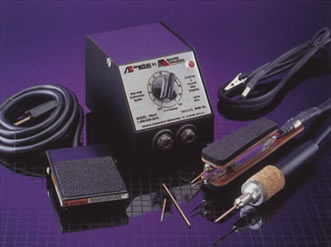 |
Description: System Description: The set consists of a Model 105A3 (100 watt) Power Unit, a Model 10541 Tweezers-style Handpiece, a Model 10515 Single Carbon Electrode Handpiece, a Model 10512A Ground (current-return) Lead, Model 10542 spare Electrodes and a Model 10519 Footswitch. This set has been selected for use by modelers and will handle most of the applications that you will encounter. For more detailed information please read the Information/Instruction sheets included with the Power Unit and Handpieces in this Kit.
Replacement Electrodes/Elements: Model 10565 |
Uses:
- System Set Up: Plug the Power Unit into the Footswitch receptacle, plug the Footswitch into a properly grounded 120 VAC outlet. Depress and hold the footswitch; the pilot light will come on indicating that the unit has power. The light will go out when the Footswitch is released. The Handpieces and Ground (current-return) Lead are fitted with taper pin quick connect terminals for connection to the Power Unit (push in turning clockwise until snug). There is no concern for polarity as the Power Unit delivers alternating current. The Tweezers have a two-wire cable that connects to the sockets on the Power Unit. The Single Carbon Handpiece plugs into one socket and the Ground (current-return) Lead plugs into the other. Locate the Ground (current-return) Lead clip as close as possible to the joint to be soldered. Make sure that all connections are tight and that the Electrodes are firmly seated in the Handpiece via the setscrews. The Electrodes are made from stainless steel or carbon and have a copper jacket. Only the core of the Electrode is to touch the workpiece. If necessary, dress back the copper with a file to insure that the copper jacket does not come into contact with the workpiece. Electrodes may be shaped to better accommodate an application. Stainless steel Electrodes can be bent, flattened, notched or slotted. Carbon Electrodes can be filed but not bent or flattened. Do not attempt to use Carbon Electrodes in a Tweezers as they have little lateral strength and will break when lateral force is applied.
- Recommended Soldering Procedure: Your equipment is now ready for use. Determining the proper power setting and whether to use the Tweezers or Single Carbon Electrode Handpiece for a specific application will be dictated primarily by the workpiece and then by your personal preference. Experimenting on scrap pieces with both set-ups until you become comfortable using either is strongly recommended. Know what to expect before beginning work on valuable materials or components. The procedure is simple, contacting the workpiece with the Electrodes depress and hold the Footswitch. Apply solder to the joint as it heats and release the Footswitch when the solder flows. Allow the joint to cool undisturbed until the solder sets. Exercise caution when working with solder, wear eye protection and do not touch parts until they have cooled. Avoid inhaling fumes generated by solder and flux.
- Procedure Refinement: Using test pieces that are the same size and material as the workpiece, is the best method for determining the proper power setting for an application. Set the Power Unit at 50% and solder, noting the time required to flow evenly in the joint. Work up and down the dial in 5% increments until you find the high and low extremes. you can then decide on your preferred setting between these points. Your goal is the fastest setting at which you are comfortable. A low power setting with excessive time tends to allow heat-sinking into areas adjacent to the joint. High settings can produce run times so short that you have no measure of control. We do not recommend run times less than one second. Power units set higher than 50% require a 50% duty cycle, meaning the unit must rest for a time equal to the run time before soldering another joint. Never run the unit continuously on any power setting for more than 20 seconds. If you cannot get a joint to solder in that amount of time, the work is too large for the unit or there is a problem in the set up or approach. Check the Electrodes and connections. When soldering pieces of greatly different size, consider tinning each piece separately and joining them by reflowing the solder, adding just enough new solder to complete the joint. Reflow soldering is relatively easy with resistance equipment. Trial and error may seem time consuming at first, but you will find that as you become more accustomed to the equipment you will be able to predict run times with less trial and error and that you will pick up speed in soldering. Practice does make perfect.
|
| |
| Model 105HCM - Standard Capacity Resistance Soldering Hobby System |
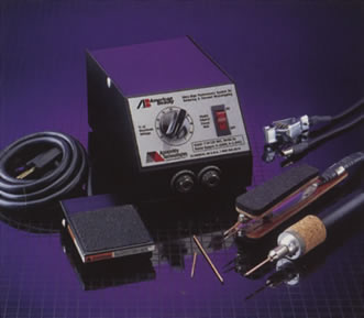 |
Description: System Description: The set consists of a Model 105A12 (250 watt) Power Unit, a Model 10541 Tweezers-style Handpiece, a Model 10515 Single Carbon Electrode Handpiece, a Model 10512A Ground (current-return) Lead, Model 10542 spare Electrodes and a Model 10519 Footswitch. This set has been selected for use by modelers and will handle most of the applications that you will encounter. For more detailed information please read the Information/Instruction sheets included with the Power Unit and Handpieces in this Kit.
Replacement Electrodes/Elements: Model 10542, Model 10530 |
Uses:
- System Set Up: Plug the Power Unit into the Footswitch receptacle, plug the Footswitch into a properly grounded 120 VAC outlet. Depress and hold the footswitch; the pilot light will come on indicating that the unit has power. The light will go out when the Footswitch is released. The Handpieces and Ground (current-return) Lead are fitted with taper pin quick connect terminals for connection to the Power Unit (push in turning clockwise until snug). There is no concern for polarity as the Power Unit delivers alternating current. The Tweezers have a two-wire cable that connects to the sockets on the Power Unit. The Single Carbon Handpiece plugs into one socket and the Ground (current-return) Lead plugs into the other. Locate the Ground (current-return) Lead clip as close as possible to the joint to be soldered. Make sure that all connections are tight and that the Electrodes are firmly seated in the Handpiece via the setscrews. The Electrodes are made from stainless steel or carbon and have a copper jacket. Only the core of the Electrode is to touch the workpiece. If necessary, dress back the copper with a file to insure that the copper jacket does not come into contact with the workpiece. Electrodes may be shaped to better accommodate an application. Stainless steel Electrodes can be bent, flattened, notched or slotted. Carbon Electrodes can be filed but not bent or flattened. Do not attempt to use Carbon Electrodes in a Tweezers as they have little lateral strength and will break when lateral force is applied.
- Recommended Soldering Procedure: Your equipment is now ready for use. Determining the proper power setting and whether to use the Tweezers or Single Carbon Electrode Handpiece for a specific application will be dictated primarily by the workpiece and then by your personal preference. Experimenting on scrap pieces with both set-ups until you become comfortable using either is strongly recommended. Know what to expect before beginning work on valuable materials or components. The procedure is simple, contacting the workpiece with the Electrodes depress and hold the Footswitch. Apply solder to the joint as it heats and release the Footswitch when the solder flows. Allow the joint to cool undisturbed until the solder sets. Exercise caution when working with solder, wear eye protection and do not touch parts until they have cooled. Avoid inhaling fumes generated by solder and flux.
- Procedure Refinement: Using test pieces that are the same size and material as the workpiece, is the best method for determining the proper power setting for an application. Set the Power Unit at 50% and solder, noting the time required to flow evenly in the joint. Work up and down the dial in 5% increments until you find the high and low extremes. you can then decide on your preferred setting between these points. Your goal is the fastest setting at which you are comfortable. A low power setting with excessive time tends to allow heat-sinking into areas adjacent to the joint. High settings can produce run times so short that you have no measure of control. We do not recommend run times less than one second. Power units set higher than 50% require a 50% duty cycle, meaning the unit must rest for a time equal to the run time before soldering another joint. Never run the unit continuously on any power setting for more than 20 seconds. If you cannot get a joint to solder in that amount of time, the work is too large for the unit or there is a problem in the set up or approach. Check the Electrodes and connections. When soldering pieces of greatly different size, consider tinning each piece separately and joining them by reflowing the solder, adding just enough new solder to complete the joint. Reflow soldering is relatively easy with resistance equipment. Trial and error may seem time consuming at first, but you will find that as you become more accustomed to the equipment you will be able to predict run times with less trial and error and that you will pick up speed in soldering. Practice does make perfect.
|
| |
|
| Model 105HHH - Deluxe Resistance Soldering Hobby System with Grounding Vise |
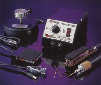 |
System Description: The set consists of a Model 105A12 (250 watt) Power Unit, a Model 10541 Tweezers-style Handpiece, Model 10542 Electrodes, a Model 10515 Single Carbon Electrode Handpiece, Model 10530 Electrodes, a Model 10512 Ground (current-return) Lead, a Model 105V12 Grounding Vise and a Model 10519 Footswitch. This set has been selected for use by modelers and will handle most of the applications that you will encounter. For more detailed information please read the Information/Instruction sheets included with the Power Unit and Handpieces in this Kit..
Replacement Electrodes/Elements: Model 10542, Model 10530 |
Uses:
- System Set Up: Plug the Power Unit into the Footswitch receptacle, plug the Footswitch into a properly grounded 120 VAC outlet. Turn the Power Unit on, using the lighted rocker switch. Depress and hold the Footswitch, the lighted rocker should illuminate, indicating that the unit has power. The light will go out when the Footswitch is released. The Handpieces and Ground (current-return) Lead are fitted with taper pin quick connect terminals for connection to the Power Unit (push in turning clockwise until snug). There is no concern for polarity because the output is alternating current. The Tweezers have a two-wire cable that connects to the sockets on the Power Unit. The Single Carbon Handpiece plugs into one socket and the ground lead plugs into the other. Locate the ground lead clip as close as possible to the joint to be soldered. Make sure that all connections are tight and that the Electrodes are firmly seated in the Handpiece via the setscrews. The Electrodes are made from stainless steel or carbon and have a copper jacket. Only the core of the Electrode is to touch the workpiece. If necessary, dress back the copper with a file to insure that the copper jacket does not come into contact with the workpiece. Electrodes may be shaped to better accommodate an application. Stainless steel Electrodes can be bent, flattened, notched or slotted. Carbon Electrodes can be filed but not bent or flattened. Do not attempt to use Carbon Electrodes in a tweezers as they have little lateral strength and will break when lateral force is applied.
- Recommended Soldering Procedure: Your equipment is now ready for use. Determining the proper power setting and whether to use the Tweezers or Single Carbon Electrode Handpiece for a specific application will be dictated primarily by the workpiece and then by your personal preference. Experimenting on scrap pieces with both set-ups until you become comfortable using either is strongly recommended. Know what to expect before beginning work on valuable materials or components. The procedure is simple, contacting the workpiece with the Electrodes depress and hold the Footswitch. Apply solder to the joint as it heats and release the Footswitch when the solder flows. Allow the joint to cool undisturbed until the solder sets. Exercise caution when working with solder, wear eye protection and do not touch parts until they have cooled. Work in a well-ventilated area and avoid inhaling fumes generated by solder and flux.
- Procedure Refinement: Using test pieces that are the same size and material as the workpiece, is the best method for determining the proper power setting for an application. Set the Power Unit at 50% and solder, noting the time required to flow evenly in the joint. Work up and down the dial in 5% increments until you find the high and low extremes. You can then decide on your preferred setting between these points. Your goal is the fastest setting at which you are comfortable. A low power setting with excessive time tends to allow heat-sinking into areas adjacent to the joint. High settings can produce run times so short that you have no measure of control. We do not recommend run times less than one second. Power Units set higher than 50% require a 50% duty cycle, meaning the unit must rest for a time equal to the run time before soldering another joint. Never run the unit continuously on any power setting for more than 20 seconds. If you cannot get a joint to solder in that amount of time, the work is too large for the unit or there is a problem in the set up or approach. Check the Electrodes and connections. When soldering pieces of greatly different size, consider tinning each piece separately and joining them by reflowing the solder, adding just enough new solder to complete the joint. Reflow soldering is relatively easy with resistance equipment. Trial and error may seem time consuming at first, but you will find that as you become more accustomed to the equipment you will be able to predict run times with less trial and error and that you will pick up speed in soldering. Practice does make perfect.
|
| |
|